Meter for active power, but measuring reactive power!!!!! Strange but true. Let's see how wattmeter measures reactive power!!!!!!
It may looks strange but yes we can measure reactive power by wattmeter. In the last article we have shown how we can measure three phase active power by using two Wattmeter. You can check the article here.
In this article we will discuss how to measure reactive power by Wattmeter.
Before starting to the topic one thing to be noted that the torque produced in a wattmeter is due to the product of current passing through the current coil, voltage across the voltage coil and cosine of the angle between the voltage and current. Hence watt meter reading indicates the active power since active power is the cosine component of voltampere.
However this principle shall be used to measure reactive power only by applying a small trick on the connection.
Reactive power Q=3.Vp.Ip.Sin A.......(1)
Or, Q=√3.Vl-l.Il.Sin A............................(2)
Where,
Vp= Phase voltage
Vl-l=Line to line voltage
Ip= Phase current
Il=Line current
And
A=Power factor angle. We presumed the load to be lagging.
Now
for delta connected system Vl-l=Vp and Il=√3Ip.
For star connected system Vl-l=√3Vp and Il=Ip
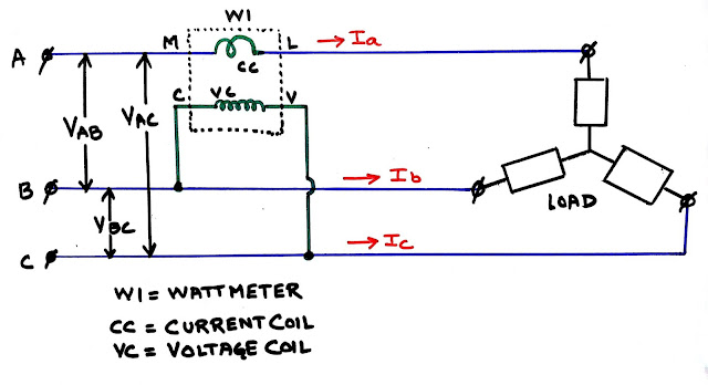
Now let us have look on the circuit diagram and system phasor diagram.
 |
| Fig 1:Circuit diagram for reactive power measurement by wattmeter/ https://electricaltechnologyrishi.blogspot.com |
So from the above image we can see that the current coil is connected in line A, so it will measure current Ia.
The voltage coil is connected between line B and C. So it will measue voltage Vbc.(In the pictures the suffixs are shown in capital. However case of the suffixs are irrelevant i.e. Vbc and VBC signifies same vector).
And also the meter deflection will be effected by cosine of angle between vector Vbc & Ia.
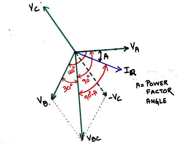
To identify the angle we have to see the vector diagram. Let's have a look below.
 |
| Fig 2: Phasor diagram of a three phase system for reactive power measurement/ https://electricaltechnologyrishi.blogspot.com |
So from the phasor digram we can see that phasor Vbc is lagging Va by 90 degree. And Ia is lagging Va by angle A.
So angular difference between Vbc and Ia is 90-A.
However please note that this condition will vary according to the circuit connection. If the current coil is connected to line B and voltage coil is connected across line A and C the representation shall be different. So careful with the circuit.
Now as per our circuit the measured power is=Vbc.Ia.Cos(90-A)=Vbc.Ia.Sin A.
Now note that Vbc is line to line voltage, and Ia is also line current.
So as per the equation no (2) multiplying the wattmeter reading by √3 we will get the desired reactive power.
So this is the method by which we can find out the reactive power by using wattmeter.
Hope you have enjoyed this article. Please share your opinion in the comment box. And for all of our other posts please visit the page "Site Map"
Thank you.......


But he’s trying none the less. I’ve been using Movable-type on several websites for about a year and am anxious about switching to another platform.
ReplyDeleteindustrial safety course in chennai
Sir how can find the reactive power when the wattmeter 's reading is given as W1 and w2 in case of three phase ..plz reply 👏👏👏
ReplyDeleteThanks for sharing such a nice information. Keep posting !!!Attache Handle
ReplyDeleteAttache Handle Manufacturer in Delhi
ReplyDeleteHello there, this is amazing blog i really appriciated. thats great you are good writer
Click here
Click here
Click here
Click here
Click here
Click here
Click here
Click here
Thank you
1 wattmeter mai neutral ka hona jaruri hai
ReplyDeleteAapke neutral ka pta hi nhi