
SELECTION OF PROPER CURRENT TRANSFORMER IS ONE OF THE IMPORTANT PART OF A PERFECT PROTECTIVE SYSTEM. IF THE PROTECTION IS DONE BY DIFFERENTIAL THEN IT HAS THE MOST IMPORTANCE.....
In the previous article "Restricted Earth Fault Protection-CT SELECTION-PART 1 :RATIO SELECTION" we have seen methods of CT ratio selection for REF protection. In this artcle we shall learn how the other parameters like knee point voltage and stabilizing resistors are selected.
Installation location of CT and the restricted earth fault (REF) relay have a very important role in knee point voltage selection, also stabilizing resistor design. Let's see how.
A transformer connects an H.V & L.V system. Restriced earth fault relay shall trip the transformer feeder breaker, i.e. primary(power receiving or input winding) side circuit breaker of the transformer to ensure fault isolation. Because if there is a fault inside the secondary winding (power delivering or output) isolation of lv side breaker will not isolate the fault, only tripping of primary side breaker will isolate it.
So it is obvious that trip signal of REF relay shall be given to primary side breaker that is the transformer feeder breaker. Now there remains the question where the relay & CTs will be installed.
Installation of REF relay:
Relay can be installed either in the LV or HV side switchgear or relay panel depending upon their location. If both HV and LV switchgear panels or relay panels are located in same room or very near then we can place the relay at hv switchboard or relay panel. But if they are located far then???
Suppose we have an 11 kV switchboard at location A, 11/0.433 kV transformer and 415 V switchboard at location B. Location A and B are say 400 m apart. Then we will install the REF at LV switchboard and from there we shall drag the trip signal to HV side.
The objective shall be MINIMIZING the cable length between CT AND RELAY.
Because this cable length (basically cable resistance) will cause high knee point voltage.
Installation of the current transformer:
Neutral CT can be installed either in transformer neutral bushing or NGR panel(if applicable). Both are closer to the transformer.
But the line CTs can be installed either in the line bushing or in the secondary switchgear. If the line CTs are located at transformer bushing then REF will only detect fault inside the transformer. But if it located in the secondary switch gear(generally LV switchgear) then the cable or bus duct connecting the transformer secondary and LV switchgear will also come under the restricted zone. So any earth fault happening here shall also be detected by REF. Both installation are used in industry.
Let us see the typical REF installation.
 |
| FIG 1:CT CONNECTION FOR REF_CT AT TRAFO BUSHING & RELAY AT FEEDER SWITCHGEAR/https://electricaltechnologyrishi.blogspot.com |
In the above picture Line CTs are installed at transformer bushing, and the relay is installed at HV switchgear. This type of arrangement is possible when HV, LV switchgear & transformer are located adjacent to each other. Trip Signal of the relay is wired to the HV/primary side circuit breaker.
 |
| FIG 2:CT CONNECTION FOR REF_CT AT LV SWITCHGEAR & RELAY AT FEEDER SWITCHGEAR/ https://electricaltechnologyrishi.blogspot.com |
Here the CTs are installed at LV switchboard, and the relay is installed at HV switchgear. This type of arrangement is also possible when all the Switchboard and transformers are adjacent to each other. Only difference with the previous one is that here the Secondary terminal to switchboard connector (Cable or Bus duct) is also under REF protection zone. Trip Signal of the relay is wired to the HV/primary side circuit breaker.
 |
| FIG 3:CT CONNECTION FOR REF_CT AT TRAFO BUSHING & RELAY AT LV/SECONDARYSWITCHGEAR/https://electricaltechnologyrishi.blogspot.com |
In this type of arrangement LCTs are installed at transformer bushing & relay is installed at LV switchgear. This type of arrangement is done when HV switchgear is located away from the transformer and LV switchgear. Trip signal from the relay is taken to the HV breaker by control cable. However length of this cable is not a concern to us.
 |
| FIG 4:CT CONNECTION FOR REF_CT & RELAY AT LV SWITCHGEAR/ https://electricaltechnologyrishi.blogspot.com |
In the above arrangement LCT and relay both are at LV switchgear. It is also executed when HV switchgear is away from the transformer.
In all the pictures the control cables (shown in RED colour) connecting the relay and the CTs shall effect the knee point voltage, that is why this length shall be minimized as possible.
KNEE POINT VOLTAGE:
As per IEC rated knee point voltage of a CT can be defined as the minimum power frequency sinusoidal voltage (r.m.s) applied to the secondary of the CT, with all other terminals remain open circuited, when increased by 10% doesn't cause increasing of magnetizing current by not more than 50%.
Basically it means that upto the knee point voltage linear relation between magnetizing current and voltage is maintained.
Why it is important for restricted earth fault protection?
The first thing to be remembered that CT for ref protection shall be operated in the liner zone of the CT.
So it is to be ensured that under no operating condition voltage across the CTs shall cross their knee point voltage.
As mentioned in the article Restricted Earth Fault Protection Philosophy REF detects fault within a selected zone, and remains non responsive for fault out side of the zone, we must check the situations to identify which type of fault outside of the protection zone can cause the relay to mal-operate.
As mentioned in the above said article earth fault outside of the protection zone will not be detected as both line CT and neutral CT will sense same current, hence a differential current of 0 A. But what will happen for a phase through fault?
Phase through fault means a phase fault outside of the protection zone.
You must be thinking that for phase fault the line CTs being resudually connected will not deliver any current to the relay. It is actually pratially true. The CTs may not deliver current directly as per the ratio, but when a large current will pass through the CT a voltage called "Stabilizing Voltage" will appear across the CT terminal.
This voltage shall drive a current through the relay coil if proper measures are not taken.
Calculation of stabilizing voltage:
Stabilizing voltage across a CT is defined as
Vs=(If/N)*(Rct+2RL)
Vs=Stabilizing voltage across the CT terminal
If=Actual through fault current
If=Actual through fault current
N=CT turn ratio
Rct=Resistance of the CT
RL=Lead resistance, basically resistance of the cable connecting the CT and the relay. 2*RL is considering return path.
Knee point voltage of the CT shall be MINIMUM 2 times of Vs.
So, from the above expression we can see that Rct & RL effect the knee point voltage. That's why Rct is specified upto a limit of 5 ohm, and measures is taken to minimize the length of the cable between relay & CT. Sometimes higher cross section of cables are used to minimize the cable lead resistance. Because CT with higher knee point voltage will occupancy more space, as it has a bulky design.
Now let us see a typical example.
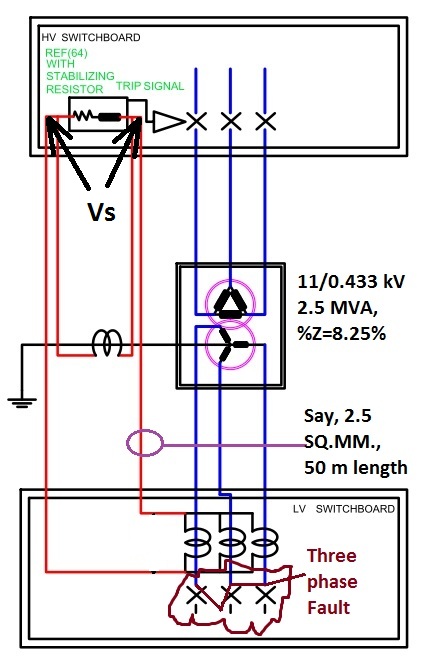 |
| Fig 5:CT CONNECTION FOR REF_ CALCULATION OF STABILIZING VOLTAGE /https://electricaltechnologyrishi.blogspot.com |
Say a three phase fault has occurred out side of the protection zone. Maximum length from CT to relay is 50 M for one run, so for return it will be another 50 M.
Fault KVA=2.5*1000/0.0825
=30303 KVA
Fault current=30303/(1.732*0.415)
=42160A (Approx.)
CT ratio taken as 4000/1A=4000
Hence N=4000
Rct=5 Ohm (Specified)
A standard Copper cable of X section of 2.5 sq. mm. has a resistance of 9.5 Ohm/km.
So, for 50 m length the resistance shall be 9.5*0.05=0.475 Ohm.
So for to an fro run the resistance shall be 2*0.475=0.95 Ohm.
Hence Vs=(42160/4000)*(5+0.95)=62.713 V
(If this valu goes beyond 3 kV another non linear resistance called METROSIL will be required in parallel with the relay circuit. Detail discussion is beyond scope of this article)
So, Knee point Voltage shall be minimum 2*62.713=125.426 V. Say we select a Ct with Vk=200 V. But this to be remembered that the cable length may increase as per the cable route layout. Hence it is always advisable to keep adequate margin on Knee point voltage.
So, thus Knee point voltage is selected to ensure operation of the REF in linear zone of the CT. But this accumulated voltage will drive current through the relay coil causing mal-operation of the relay. Here comes the importance of stabilizing resistor.
Suppose an REF relay has a minimum pick up of 0.05 A, we select this setting, so that it can detect earth fault current at the maximum possible for the relay.
So the relay will pick up for 0.05 A current. The Line CTs have 62.713 V across its terminal during a through phase fault. So we have to add a resistor which will restrict current below 0.05 A for that stabilizing voltage.
Suppose the relay has a burden of 1 VA, then value of the Stabilizing resistor shall be
Rs=(Vs/Ir)-(VA/Ir^2)
Vs=Stabilizing Voltage
Ir= Relay pick up current
VA= Burden of the relay
Rs=(62.713/0.05)-(1/0.05^2)
=854.26 Ohm or higher.
Addition of this resistor will not let the relay to operate during a through fault. Thus the restricted zone shall be maintained.
So this completes selection of CT for REF protection. It also covers the setting of REF. Basically minimum setting to REF relay shall ensure that fault at very small percentage of winding will be detected that is it enhances sensitivity of the relay.
Hope you have enjoyed this article. Please share your opinion in the comment box. And for all of our other posts please visit the page "Site Map"
Thank you.......


good articles, include more depth topic
ReplyDeleteThanks.. This covers most of the fundamental philosophy. If you have any specific doubt, please feel free to ask. I shall try my best to answer.
DeleteIn your case you considered a 3 phase out zone fault to calculate the Vs. What will happen if an neutral grounding resistor is used at the N terminal of the transformer. Still you use the same 3 phase through fault current or single line to earth fault current in order to calculate Vs. (My question is if an NGR is used what is the implication in your above calculation of Vs )
ReplyDeleteVery nice information.
ReplyDeleteRead More Article
This can all be picked up at a arts and crafts store either online or offline. It is very crucial that you wear safety goggles when cutting glass. You may think its overkill, its always better to be safe when cutting glass. gözlüğü
ReplyDeleteWriting with style and getting good compliments on the article is quite hard, to be honest. But you've done it so calmly and with so cool feeling and you've nailed the job. This article is possessed with style and I am giving good compliment. Best! Fault Location Services Greenbelt
ReplyDeleteYou ought to basically fantastic not to mention solid advice, which means notice Fault Location Services George Mason
ReplyDeleteI wanted to thank you for this great read!! I definitely enjoying every little bit of it I have you bookmarked to check out new stuff you post. Fault Location Services Mantua
ReplyDeletenice post. very well explained in a simple language
ReplyDeleteI truly appreciate this post. I have been looking everywhere for this! Thank goodness I found it on Bing. You have made my day! Thank you again 2cl77
ReplyDeleteNice Post
ReplyDeleteThis site is a truly a study material for electrical engineering students, Thank you for earth fauth protection blog. Important Power contactors list given below
ReplyDeleteContactor 25 Amp
Contactor 32 Amp
Contactor 40 Amp
Contactor 50 Amp
Looking for- https://coraductcleaning.com Best Duct Cleaning in Toronto, must visit Cora.
ReplyDelete