TRANSFORMER IS THE MOST USED ELECTRICAL EQUIPMENT IN INDUSTRY. LET US SEE A DIAGRAMMATIC REPRESENTATION OF ITS WORKING PRINCIPLE, CALLED "PHASOR DIAGRAM" ALSO KNOWN AS "VECTOR DIAGRAM"
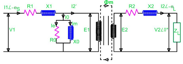
Before starting the "Phasor Diagram" we should know how electrical model of a transformer looks. It is called Equivalent circuit of a transformer.
 |
| EQUIVALENT CIRCUIT OF TRANSFORMER/ https://electricaltechnologyrishi.blogspot.com |
Now let us see what are the parameters used:
ZL=Load Impedance (in generally of inductive nature)
I2= Secondary Current or Load Current, Since the load is inductive current shall be lagging in nature.
V2=Secondary Terminal Load Voltage. (We shall consider this as our reference, hence its position has been selected as 0 degree)
R2=Resistance of the secondary winding
X2=Inductance of the secondary winding
E2=Induced voltage at secondary winding
E2=V2+I2(R2+jX2) (Vector addition), In case I2=0 i.e. trafo is on no load this E2 will appear at transformer terminal as no load voltage
E1=Induced voltage at primary winding
E1=(T1/T2) X E2
Φ m=Maximum value of linked flux (Flux responsible for induced voltage i.e. E2 & E1)
I2'=Current at Primary winding due to secondary current=(T2/T1) X I2
R0 & X0=equivalent Loss component & magnetizing inductance component.
Ie=Loss component of the No load current, responsible for core loss
Im=Magnetizing current, responsible for flux generation
I0=No-Load current
I0=Ie+Im(Vector addition)
R1=Resistance of the Primary winding
X1 Inductance of the Primary winding
I1=Primary Current
I1=I0+I2'(Vector addition)
V1=Primary applied terminal voltage
V1=E1'+I1(R1+jX1)(Vector addition)
Now Let us start Construction of the transformer phase diagram.It will be easier to understand the phasor diagram and transformer's working principle it secondary terminal Load voltage i.e. V2 is taken as reference phasor. Lets See.
Transformer Phasor Diagram_Step 1:
V2 as reference phasor |
| Fig 1: Transformer phasor diagram V2 as reference/ https://electricaltechnologyrishi.blogspot.com |
Transformer Phasor Diagram_Step 2:
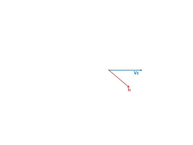
I2 is lagging the load voltage i.e. V2
 |
| Fig 2: Transformer phasor diagram I2 is lagging V2/ https://electricaltechnologyrishi.blogspot.com |
 |
| Fig 3: Transformer phasor diagram_ Angle between V2 and I2 is load power factor angle/ https:electricaltechnologyrishi.blogspot.com |
Transformer Phasor Diagram_Step 3:
Voltage drop due to resistace of the secondary winding shall be parallel with Load current, as resistance doesn't cause any phase angle displacement. Since we have started our phasor diagram from the terminal load voltage so we shall add this voltage drop with the terminal voltage V2.I2R2 ,parallel with I2 added with V2.
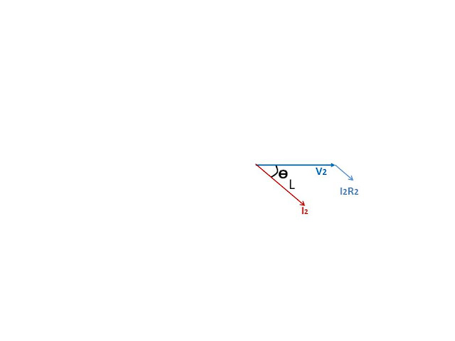 |
| Fig 4: Transformer phasor diagram_Resistive voltage drop is in parallel with I2/ https://electricaltechnologyrishi.blogspot.com |
Transformer Phasor Diagram_Step 4:
Add I2X2 drop with I2R2 drop. As inductive voltage leads current by 90 degree hence I2X2 drop shall be 90 degree leading from I2 i.e. I2R2 phasor. |
| Fig 5: Transformer phasor diagram_Inductive voltage drop is in 90 degree leading with I2/ https://electricaltechnologyrishi.blogspot.com |
Transformer Phasor Diagram_Step 5:
Sum of V2, I2R2, I2X2 shall form induced voltage at secondary winding i.e. E2. As mentioned this is a vector sum which can be seen from the below picture. If the transformer is unloaded then this voltage will appear at the transformer terminals. Hence it is No lad voltage also. which is higher than the Terminal load Voltage.A transformer is rated with its secondary no load voltage. for example for supplying 415 V load voltage you will have to select secondary no load voltage higher than 415 V. n practice this shall be 433 V. So a 11/0.433 kV transformer means it will step down the voltage from 11 kV to 0.433 kV at no load. Depending upon the load secondary load voltage shall be determined. This transformer shall never be specified as 11/0.415 kV. for getting 6.6 kV output transformer secondary rating shall be 6.9 kV.
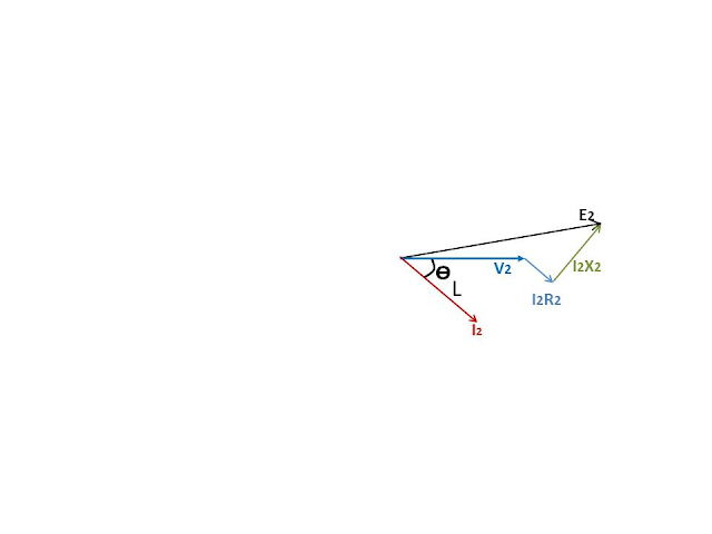 |
| Fig 6: Transformer phasor diagram_Computation of Secondary induced voltage or no load terminal voltage/ https://electricaltechnologyrishi.blogspot.com |
Transformer Phasor Diagram_Step 6:
Determination of maximum flux. Since the voltage induced in transformer is due to the change of flux hence it shall lag the flux by 90 degree. Lets see how.
The in the core is sinusoidal.
Φ =
E2=dΦ /dt=d/dt(Φ m Sin wt)=Φ m Cos wt=Φ m Sin(wt-90)
this derivation indicates that induced voltage lags behind the flux by 90 degree. hence we can say the flux leads the induced voltage by 90 degree.
So we will add the flux phasor 90 ahead of E2.
 |
Fig 7: Transformer phasor diagram_flux leads induced voltage by 90 degree/
https://electricaltechnologyrishi.blogspot.com
|
Transformer Phasor Diagram_Step 7:
Induced voltage at primary winding shall also lag the flux by 90 degree. However its magnitude shall be E1=(T1/T2)*E2
 |
Fig 8: Transformer phasor diagram_Primary induced voltage lags the flux by 90 degree/
https://electricaltechnologyrishi.blogspot.com
|
Transformer Phasor Diagram_Step 8:
The flux is generated by magnetizing current. So both of them shall be in phase. Im is in phase with the flux.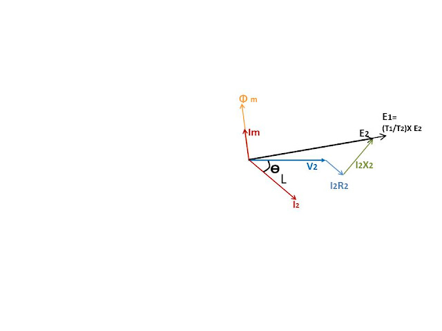 |
Fig 9: Transformer phasor diagram_Magnetizing current shall be in phase with flux./
https://electricaltechnologyrishi.blogspot.com
|
Transformer Phasor Diagram_Step 9:
No load loss component.Magnetizing current is an inductive current and no load loss component is resistive current. So loss component will lead magnetizing current. As inductive current lags behind the resistive current by 90 degree, when both resistance and inductance purely resistive and inductive respectively.
 |
Fig 10: Transformer phasor diagram_No load loss component current shall be 90 degree leading of the flux/
https://electricaltechnologyrishi.blogspot.com
|
Transformer Phasor Diagram_Step 10:
No load current.Vector Sum of Im & Ie shall give I0 i.e. the no load current. From the equivalent circuit also you can see that this current will always flow through the transformer even if the secondary is open circuited.
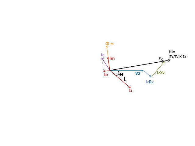 |
Fig 11: Transformer phasor diagram_No load current/
https://electricaltechnologyrishi.blogspot.com
|
Transformer Phasor Diagram_Step 11:
Computation of Primary Current or I1From the equivalent circuit it is clear that primary current is vector sum of No load current (I0) and reflection of secondary current to the primary(I2')
I2'=(T2/T1)*I2
And it shall be exactly 180 degree opposite to I2
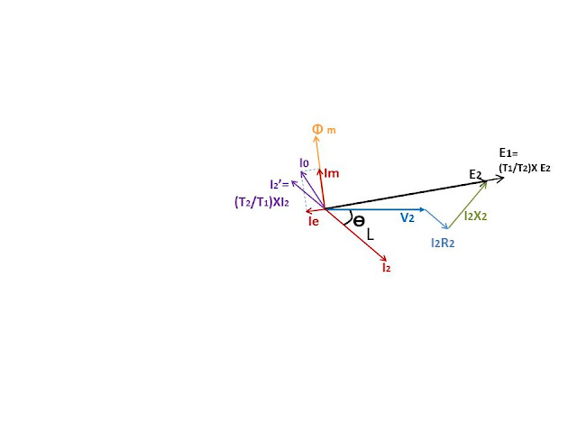 |
Fig 12a: Transformer phasor diagram_I2 reflected to primary/
https://electricaltechnologyrishi.blogspot.com
|
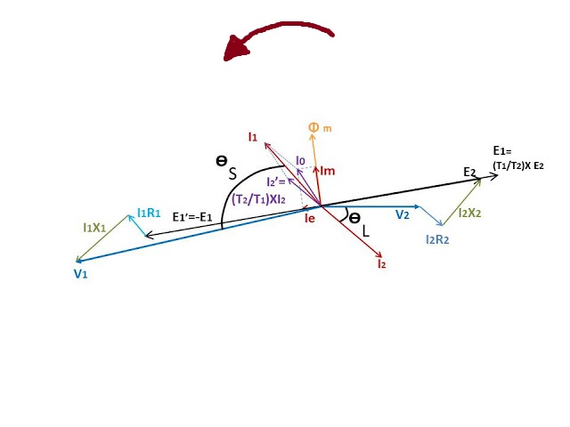
Vector sum of I2' & I0 shall give I1 i.e. Primary current.
 |
Fig 12b.: Transformer phasor diagram_Primary current I1/
https://electricaltechnologyrishi.blogspot.com
|
Transformer Phasor Diagram_Step 12:
Computation of Input Voltage & Primary induced voltageAs mentioned earlier Primary induced voltage E1=(T1/T2)*E2.
Now reflect it to primary side.
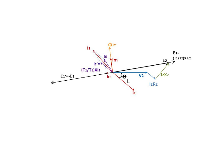 |
Fig 13a.: Transformer phasor diagram_Primary induced voltage E1 reflected to primary/
https://electricaltechnologyrishi.blogspot.com
|
 |
Fig 13b.: Transformer phasor diagram_I1R1 drop added with E1'/
https://electricaltechnologyrishi.blogspot.com
|
 |
Fig 13c.: Transformer phasor diagram_I1X1 drop added with I1R1/
https://electricaltechnologyrishi.blogspot.com
|
 |
Fig 13c.: Transformer phasor diagram_V1/
https://electricaltechnologyrishi.blogspot.com
|
Transformer Phasor Diagram_Step 13:
Source power factorAngle between V1 & I1 is source power factor angle. From the phasor diagram we can see that Source power factor angle is higher than load power factor angle. hence source power factor shall be less than load power factor.
 |
Fig 14.: Transformer phasor diagram_Source power factor angle/
https://electricaltechnologyrishi.blogspot.com
|
COMPLETE TRANSFORMER PHASOR DIAGRAM
So, by these we can draw the phasor diagram of a transformer. Understanding of this is very important for understanding the transformer working principle.
Hope you have enjoyed this article. Please share your opinion in the comment box. And for all of our other posts please visit the page "Site Map"
Thank you.......



Very nice information.
ReplyDeleteRead More Article
Thanks for sharing such wonderful Post.
ReplyDeleteGreat diagram and i was also looking for this diagram.
ReplyDeleteUltimate post by you.
Transformer Manufacturers in India
Transformer manufacturers in Bangalore
Transformer manufacturer in Delhi
Thanks for sharing such good information written in a very attractive way. Your blog information improve my knowledge about Transformer.
ReplyDeleteServo Voltage Stabilizer
Transformer Manufacturer In Noida
nice info Neutral current transformer specification
ReplyDelete
ReplyDeleteNice post. It is really awesome post & Help who sharing great Blogs.partsxp group has taken to encouragement and helpfull suggetions. We are supplying household electrical parts, Drive Isolation.It is given fastest servicess & Manfacture New products.
This is my first visit to your web journal! We are a group of volunteers and new activities in the same specialty. Website gave us helpful data to work. thermal imaging melbourne
ReplyDeleteVery useful information you shared with us. thank you for sahring this information.
ReplyDeletePower Transformers in India | Transformer Manufacturer in India
The information you shared with us is very helpful. thank you.
ReplyDeletePower Transformers in India | Transformer Manufacturer in India
It's really very informative and useful post. Tate Electricals is one of the best transformer manufacturers in Pune.
ReplyDeleteThanks for sharing
ReplyDeleteTransformer Manufacturers in India
Transformer Manufacturers in Mumbai
Transformer Manufacturers in Pune
Thanks for sharing a blog.This blog is very nice.Your blogs information is real.I hope your blog are provide the real knowledge. Best Quality Distribution Transformer Exporters
ReplyDeleteNice blog. Thanks for sharing the information in transformer manufacturer.
ReplyDeleteBest Oil Immersed Power Transformer manufacturers and Supplier in India
Most people have no idea what happens to the oil when it is extracted from a nut or seed. To extend the oil's shelf life, create a clear color and remove its natural scent, it is bathed in a petroleum solvent, then "degummed" or placed in hot water and swirled at a high speed to separate out various substances. To further refine the oil, it is mixed with an alkali such as lye or caustic soda; then it is agitated, heated again, bleached, hydrogenated to stabilize it and finally deodorized. dielectric strength
ReplyDeletePython Homework Help - We help you to complete your Python coding. We provide best Python homework help in reasonable price, within your deadline.
ReplyDelete===============================
Thanks for helping us to find india's most trusted Electrical and Power Equipment Manufacturers.
ReplyDeleteServo Controlled Voltage Stabilizer Manufacturer
Automatic Voltage Controllers Manufacturers
Automatic Voltage Stabilizer Transformer
Manufacturers
Good to hear you.
ReplyDeleteTrutech Products is leading the Best Transformer Manufacturers in Mumbai at the best cost Visit Us For:
Transformer Manufacturers in India
Transformer Manufacturers in Mumbai
Thanks for sharing that wonderful post that describe how TRANSFORMER IS THE MOST USED ELECTRICAL EQUIPMENT IN INDUSTRY.
ReplyDeleteMPIL is Muskaan Power Infrastructure Ltd. which is CPRI/ERDA/BIS Approved an ISO 9001:2008 Certified Company which is supplying furnace transformers, isolation transformers, variable transformers, distribution transformers, power transformers, servo voltage stabilizers, Voltage stabilizers, industrial stabilizers, rectifiers, dc rectifiers, etc.
Our Firm is leading Manufacturer of all kind of Servo Voltage Stabilizer Manufacturers & Transformer. Explore the details of our products below.
High Tension Transformer
Three Phase Oil Cooled
Transformer
Three Phase Variable Transformer
Variable Voltage Transformer
Variable Transformers
Oil Immersed Power Transformer
Muskaan Power Infrastructure Ltd is one of the leading Brand Manufacturer company in the industry of Electrical and Power Equipment. Our Firm Established in 2003 and an ISO 9001-2000 BVQI Certified Company. We Specialize to manufacture & supply Furnace Transformers, Power Transformers, Distribution Transformers, Dry Type Transformers, etc.
ReplyDeleteServo Controlled
Voltage Stabilizer Manufacturer
Automatic Voltage Controllers
Manufacturers
Best Voltage Stabilizer Manufacturers
Air Cooled Servo
Stabilizer Manufacturers
Thank you for giving this wonderful blog.
ReplyDeleteTrutech Products is one of the best Transformer Manufacturers In India. Contact us or visit our website if you are looking for best Transformer Manufacturers in Pune.
Nice article about transformer phasor, looking forward for more blogs. Always buy genuine and branded MCB's electrical products by comparing price list
ReplyDelete16 amp mcb price
mcb 63 amp price
mcb 10 amp price
6 ampere mcb price
4 pole 63 amp mcb price
Double Pole MCB
mcb 4 pole
havells mcb 10 amp price
havells mcb 63 amp price
32 ampere mcb price
Thanks for sharing this informative blog content with us. I would like to share about Paraflex, one of the leading Copper Wire Industry in India.
ReplyDeletegreat Article On Transformer Phasor and the Diagrams Are simple and Straight to the Point.
ReplyDeleteyou Can Also Have a Look at Some Of the Top Rated Electrical Switches.
16 Amp Switch
6 Amp Switch
20 Amp Switch
SMM Instagram involves strategically utilizing the platform to promote brands, products, or services through engaging content and community-building strategies to reach and engage with a target audience.
ReplyDeleteThis blog post on "Equivalent Circuit of a Transformer" provides a detailed breakdown of key transformer parameters and their relationships, making it easier to understand the transformer’s operation and phasor diagram. Excellent for electrical engineering enthusiasts!
ReplyDeleteWe are listed among the top Industrial Transformer Manufacturer and Exporters.
ReplyDelete